Modeling and Dynamic Control of Aircraft
Steady State Flight using PID Controller
All of our analysis and modeling was done in two dimensions, along the yz-plane of the aircraft. However, the simulator contained a plane in 3 dimensions with modeled disturbances. To rectify this discrepancy, we used Simulink to create two PID loops to control the rudder and ailerons of the plane. These loops endeavored to keep the roll and yaw of the plane at a minimum, thus approximating a 2D environment with the 3D airplane.


Even though most commercial aircrafts use jet engines for propulsion, the plane that we wrote our algorithm for a DeHavilland Beaver (pictured below) uses propellers to give it thrust and this thrust force (after the angle of attack of elevators) was the second control variable that we used in our original algorithm. The resulting problem with this algorithm was that it was too complicated to successfully model and implement given the time constraints of the project. The resulting model was a MIMO (Multiple Input Multiple Output), a type of model that takes secial techniques to analyze.

Implemented Controller
In order to practice some sort of control algorithm design and implementation, we scaled back our control algorithm to hold a constant speed using only the propeller. The thinking behind this method of control is that changing the propeller RPM changes the thrust force on the plane. Controlling the RPM would thus control the velocity of the plane. This method, however, has setbacks. First, the algorithm doesn't control the elevators and thus relies on the plane's natural tendency to stabilize when changing the thrust. If the thrust changes too fast or is too large of a value, the plane pitches too far up or down and cannot recover. This algorithm thus only works for a small band of velocities close to half of the plane's top cruising velocity. A video depicting the final simulation can be seen on the Simulation page.
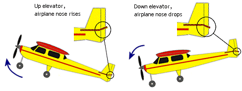
The original control algorithm that we planned to implement was a PID loop actuating the airplane's elevators and propellor and controlling the plane's altitude. The elevators are pictured to the right, embedded in the horizontal stabilizer. Generally, when you pitch the elevators up, the relative angle of attack of the tail decreases, and the tail loses lift, causing the plane to pitch up. The opposite effect happens when the elevators pitch down, causing the plane to pitch down.
