
Modeling and Dynamic Control of Aircraft
Mathematically Modeling an Aircraft
Iteration 1: Force Diagram
-
Two Degrees of Freedom
-
Assumes all forces act on Center of Mass
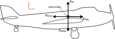
The first iteration of the plane model was a simple force diagram containing the four main forces that govern flight: drag, gravity, lift, and thrust. This model is a free body diagram, showing the four forces acting about the same point. This point is the center of mass of the aircraft This model is useful for conceptually understanding the basics of airplanes, but is not very useful for any serious modeling because it makes some large assumptions. The dynamic body depicted above has only two degrees of freedom along the x and y axes because there are no forces that can be applied to make the plane pitch, only translate.
Iteration 2: Moment Diagram
-
Three Degrees of Freedom
-
Assumes forces distributed in components about aircraft
-
Center of Mass (CoM)
-
Wing Aerodynamic Center (ACw)
-
Horizontal Stabilizer Aerodynamic Center (ACh)
-
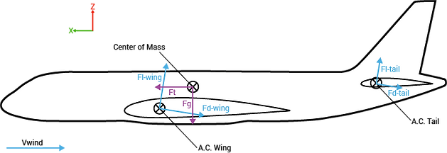
The second iteration of the model added the third degree of freedom necessary to allow control of the plane's pitch. The model includes pitch because it takes into account the different locations at which different forces act. Both lift and drag are components of the aerodynamic force projected onto the airplane's coordinate system, and act about the aerodynamic center of an object. This means that each piece of the airplane has a lift and a drag force.
The wing and horizontal stabilizer have large Lift/Drag ratios and as such the individual forces acting on them are modeled. The fuselage has a low lift-to-drag ratio, and as such its lift and drag forces are combined into a single moment about the plane's center of mass. Gravitational force still acts about the center of mass, as does force of thrust.
This model seems much more reasonable, but still lacks the ability
to be controlled in any way.
The third iteration of the model took the second iteration and added a controllable control surface angle. The elevators on the horizontal stabilizer allow for control of the airplane's pitch, and therefore its xz-position.
The aerodynamics behind the elevator is complicated both because backwash and turbulence from the front wing change its effectiveness, as does the changing shape of the overall stabilizer due to the elevator's angle. However, these complexities can be simplified by noting that changing the elevator angle approximately acts like changing the angle of attack for the horizontal stabilizer and, as such, shifts the lift graph of that surface upwards.
Iteration 3: Control Surface
-
Adding Control to Model
-
Approximates Elevator as changing Horizontal Stabilizer Angle of Attack
